Page 1 of 2 12 LastLast
Results 1 to 20 of 67

Thread: Kill switch wiring

Hybrid View

Previous Post Previous Post   Next Post Next Post
  1. #1
    Join Date
    Jul 2006
    Location
    Silicon Valley, CA
    Posts
    1,381

    Default Kill switch wiring

    I did a couple of searches on this forum and elsewhere, and found some good discussions, but really couldn't convince myself of the right thing, and I'm no electrical engineer. I'm a visually-oriented guy, so maybe using these diagrams you can all help me.

    Given the wiring diagram below, can I place a simple single-pole switch in the circuit that runs around the left and top of the diagram, either right before or right after the big 200A fuse? Or do I need one of the multi-pole switches that somehow connect into the alternator circuit?

    I'm thinking the simpler approach will work. The junction point with the 8 large fuses you see eventually leads to the ignition switch, among other places.


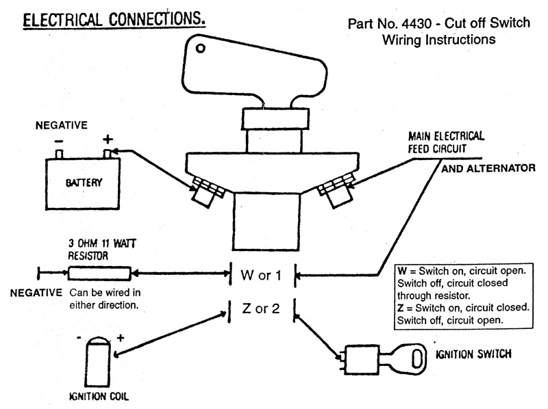
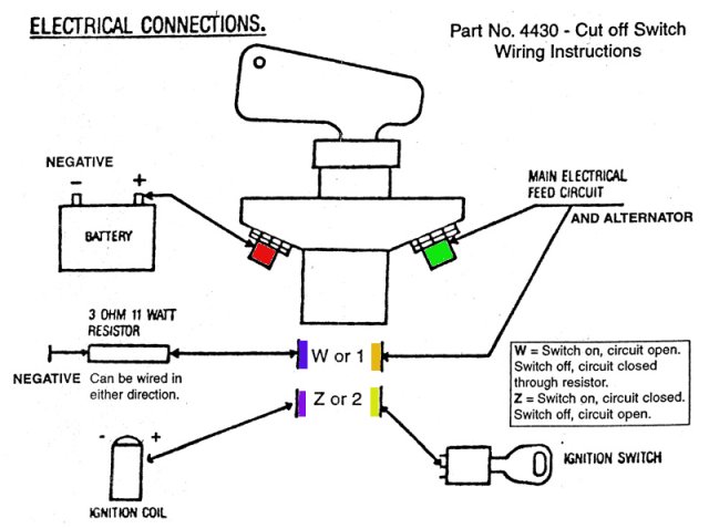
    If I need the multi-pole switch, can someone please explain to me how to wire it? I found this diagram below from Pegasus, but it's not descriptive enough for me to know what to do with it. Pegasus seems to say that all cars with alternators need these multi-pole switches, but based on what I've read elsewhere, as long as the alternator is still connected to the battery, then the single-pole switch should work?


    Thanks for the help!

    Josh Sirota
    ITR '99 BMW Z3 Coupe

  2. #2
    Join Date
    Nov 2005
    Location
    Rochester, NY
    Posts
    553

    Default

    Keep in mind that the kill switch must not only stop the engine but should isolate vehicle wiring from the battery to minimize a fire threat. The Red connection in my diagram when wired as shown, does just that. I lack enough time to give you more detail, but that Pegasus sourced diagram is concise and correct, may just be some hlepful hints for a electro-newbie!

    this may help people explain it.......


    In answer to the multi-pole switch comment. The Pegasus is 3PST 2 poles are NO and 1 pole is NC.

    The Red/Green and Violet/Yellow are N.O. and the Blue/Orange is N.C.

  3. #3
    Join Date
    Nov 2005
    Location
    Rochester, NY
    Posts
    553

    Default

    putting any electric fuel pump on the feed with the ignition coil is a good idea too.

    When you throw the Kill switch to OFF, here's what happens:

    1 - the battery is obviously otally disconnected
    2 - the ignition and fuel shut down
    3 - the alternator gets a small load to protect its diodes etc.


  4. #4
    Join Date
    Jul 2006
    Location
    Silicon Valley, CA
    Posts
    1,381

    Default

    My confusion about the Pegasus diagram is that there is no simple wire from the ignition switch to the coil in my car. My car has all sorts of fancy electronics, six ignition coils, an electronic anti-theft immobilizer, a multi-pole ignition switch with several wires on the output side, etc.

    It's just not obvious what wire to disconnect to shut the car off. I was hoping that the simpler thing would in fact kill the engine, based on, among other things, this thread.
    Josh Sirota
    ITR '99 BMW Z3 Coupe

  5. #5
    Join Date
    Nov 2005
    Location
    Rochester, NY
    Posts
    553

    Default

    My confusion about the Pegasus diagram is that there is no simple wire from the ignition switch to the coil in my car. [/b]
    Locate the group of wires that connect to the "run" position on your ignition switch, route that group through the kill switch "ignition" path.

  6. #6
    Join Date
    Jul 2006
    Location
    Silicon Valley, CA
    Posts
    1,381

    Default

    Locate the group of wires that connect to the "run" position on your ignition switch, route that group through the kill switch "ignition" path.
    [/b]
    I'm sure I could find the right thing. There is a wire at the coil packs that feeds all six, I could probably pick it up there instead of at the switch. At the switch, there is a line that's hot in run, and a line that's hot in both run & start. Seems like to kill the ignition it would be the second one. Or I could get them at the coils.

    Between the switch and the coils is so much electronics that you really can't tell what's going on.

    But ... what I really want to know is, will the first approach work? It seems like it. The alternator output side (the B+ terminal) would be connected directly to the battery, even when the switch is off, so it would have somewhere to drain. However, with the switch off, there would be no contact between the battery/alternator and the ignition. Isn't this simple approach the best approach?

    If you isolate the battery with the main circuit, and run the alternator field circuit through the normally-open circuit with the resistor, you'll be fine.
    [/b]
    Forgive me Greg ... I don't understand a word you just said! I don't know what a field circuit is, and I don't really understand what you mean by "main circuit" either.

    Can you draw me a picture?

    I understand the principle of protecting things with the resistor ... I just don't understand why the first approach doesn't do that.
    Josh Sirota
    ITR '99 BMW Z3 Coupe

  7. #7
    Join Date
    Mar 2001
    Location
    Connecticut
    Posts
    7,381

    Default

    I don't really understand what you mean by "main circuit"...[/b]
    The main circuit from the battery to the car, just as in the drawings above.

    I don't know what a field circuit is...[/b]
    VERY basically put, alternators work on the concept of comparing a circuit in the car to what voltage it's putting out, always trying to keep them equal to its setting. In the case of a 12V car, that's about 13.5 volts. If that secondary circuit, the field circuit, gets low on voltage the alternator puts out more; if it gets high, less.

    Therefore, with an alternator, if you cut off the battery only then as the field circuit voltage drops the alternator tries to out out more and more voltage. Eventually the field circuit voltage will drops too low and the alternator goes offline, but it's not instantaneous, and in the interim the alternator continues trying to charge pu the system to ~13.5V.

    However, if you open this field circuit with a switch or relay then the alternator sees zero voltage and drops offline.

    So, you can wire the car one of two ways: wire the kill switch's smaller secondary contacts such that it disconnects the field circuit and the alternator goes offline, system voltage drops to zero, and the car quits running due to lack of electrical power; or, you can wire the ignition through those secondary contacts so the car quits running and the alternaotr stops producing power due to lack of rotation.

    Either way works fine, simply choose the method that is most convenient for your car and kill switch location. - GA

  8. #8
    Join Date
    Jul 2006
    Location
    Silicon Valley, CA
    Posts
    1,381

    Default

    VERY basically put, alternators work on the concept of comparing a circuit in the car to what voltage it's putting out, always trying to keep them equal to its setting. In the case of a 12V car, that's about 13.5 volts. If that secondary circuit, the field circuit, gets low on voltage the alternator puts out more; if it gets high, less.

    Therefore, with an alternator, if you cut off the battery only then as the field circuit voltage drops the alternator tries to out out more and more voltage. Eventually the field circuit voltage will drops too low and the alternator goes offline, but it's not instantaneous, and in the interim the alternator continues trying to charge pu the system to ~13.5V.
    [/b]
    Thanks! I get it. The point of the secondary kill circuit is to reduce the amount of time it takes to get the alternator fully off-line.

    Now, just out of curiosity, what harm is caused during this duration of time if the alternator main circuit is still connected to the battery, as my original question asked?


    Josh Sirota
    ITR '99 BMW Z3 Coupe

  9. #9
    Join Date
    Nov 2005
    Location
    Rochester, NY
    Posts
    553

    Default

    My confusion about the Pegasus diagram is that there is no simple wire from the ignition switch to the coil in my car. [/b]
    Locate the group of wires that connect to the "run" position on your ignition switch, route that group through the kill switch "ignition" path.

    2nd post by accident...... how to delete??

  10. #10
    Join Date
    Jul 2006
    Location
    Silicon Valley, CA
    Posts
    1,381

    Default

    Locate the group of wires that connect to the "run" position on your ignition switch, route that group through the kill switch "ignition" path.
    [/b]
    Yeah, there is no "run" terminal of the switch. There is one terminal hot in acc/run/start, and another that's hot in run/start. (There are others too, but those are the ones used that are hot in run). The point is that there are two of them, and the switches on the market have only one.

    I still don't get why the simpler approach won't work or could cause any harm.
    Josh Sirota
    ITR '99 BMW Z3 Coupe

  11. #11
    Join Date
    May 2003
    Location
    Lagrangeville, NY
    Posts
    694

    Default

    Hey fellas. Can you check me on my wiring before I apply power? The sketch is attached.
    Attached Images Attached Images
    Chris Raffaelli
    NER 24FP

  12. #12
    Join Date
    Feb 2001
    Location
    Trussville, Alabama, USA
    Posts
    1,087

    Default

    Quick and dirty way....red battery wire to switch. Jumper from red wire to one side of aux switch. Other side of main switch to starter, etc. Other side of aux switch to wire going to feed fuse box. Done. Start and stop car with key...charge battery...kill everything with kill switch. Chuck
    Chuck Baader
    White EP BMW M-Techniq
    I may grow older, but I refuse to grow up!

  13. #13
    Join Date
    Mar 2001
    Location
    Connecticut
    Posts
    7,381

    Default

    Quote Originally Posted by chuck baader View Post
    ...kill everything with kill switch.
    And, possibly, your alternator diodes and some electronic components as well due to the surge...that's what the resistor bleed circuit is for: to slowly bleed down all potential energy (voltage), rather than simply shutting the door in its face...

    All that voltage gotta go somewhere, and if the battery isn't there to absorb the shock (its secondary purpose is to dampen voltage spikes and act as an electrical accumulator) then something will... - GA

  14. #14
    Join Date
    Feb 2001
    Location
    Trussville, Alabama, USA
    Posts
    1,087

    Default

    Greg, not to be argumentative, but I have wired 5 e30 BMWs that way with no issues. The only problems with the BMWs is when you remove the cluster..you must add a bocking diode to the circuit to replace the one removed from the alternator light. Chuck
    Chuck Baader
    White EP BMW M-Techniq
    I may grow older, but I refuse to grow up!

  15. #15
    Join Date
    Mar 2001
    Location
    Connecticut
    Posts
    7,381

    Default

    If you isolate the battery with the main circuit, and run the alternator field circuit through the normally-open circuit with the resistor, you'll be fine.

    The resistor circuit is there primarily to protect the contacts of the main circuit (and really should be used on any car, regardless of what charging system you have). If you simply open up such a high-current circuit as the battery, that load has to go somewhere; without the resistor circuit it arcs the contacts of the main switch. Giving the load someplace to slowly drain protects those contacts.

    Further, if the field circuit of an alternator stays energized (as it can with a charning system) then it can harm the alternator.

    So, by running the field circuit of the alternator through the NO circuit with resistor, you resolve both problems.

    As far as Tech is concerned, if they can reach over and shut off your car entirely with that switch (and trust me, they'll test it) then it's fine. They/we don't give two shakes what it does to the components of the charnging system; their concern is safety, your concern is making sure it doesn't hurt stuff...

  16. #16
    Join Date
    Mar 2008
    Location
    PA
    Posts
    2

    Default

    Greg, is this relevant to a dodge charger? Should I get a kill switch with the 6 terminals (2 lge, 4 sm)?

  17. #17
    Join Date
    Mar 2001
    Location
    Connecticut
    Posts
    7,381

    Default

    Quote Originally Posted by Joe Foering View Post
    Greg, is this relevant to a dodge charger? Should I get a kill switch with the 6 terminals (2 lge, 4 sm)?
    Yes, it's relevant to all cars with alternators. I strongly recommend the 6-pole kill switch, with the two large terminals for the battery circuit, the normally-open (NO) circuit for the bleed resistor, and the normally-closed (NC) circuit for the ignition circuit... - GA

  18. #18
    Join Date
    Mar 2001
    Location
    Connecticut
    Posts
    7,381

    Default

    Really, not a problem. Good mental exercise for all of us... - GA

  19. #19
    Join Date
    Oct 2005
    Posts
    114

    Default

    GUYS! keep this simple AND reliable. Let the kill swx main posts disconnect the battery.
    Let one loww current kill swx ground the grounded leg of the ignition coil, killing the engine but leaving all run consumers (fuelpump, etc) to load the alt as it coasts to a stop. (if you don't have a single coil, then put both legs of the low current circuit across the crank sensor, etc.
    Not only is this a very simple circuit, but it fails safe in regard to cutting out the engine in competition-if the low current switch gets resistive/corroded, it doesn't effect running, just killing. Phil

  20. #20
    Join Date
    Dec 2007
    Location
    West Hurley, NY
    Posts
    388

    Default

    Quote Originally Posted by pfcs49 View Post
    GUYS! keep this simple AND reliable. Let the kill swx main posts disconnect the battery.
    Let one loww current kill swx ground the grounded leg of the ignition coil, killing the engine but leaving all run consumers (fuelpump, etc) to load the alt as it coasts to a stop. (if you don't have a single coil, then put both legs of the low current circuit across the crank sensor, etc.
    Not only is this a very simple circuit, but it fails safe in regard to cutting out the engine in competition-if the low current switch gets resistive/corroded, it doesn't effect running, just killing. Phil

    Does anyone know if this simple circuit will do any harm to the MSD ignition system??
    Dan Deyo
    92 Acura Integra
    ITA #94

Bookmarks

Bookmarks

Posting Permissions

  • You may not post new threads
  • You may not post replies
  • You may not post attachments
  • You may not edit your posts
  •