-

Keep in mind that the kill switch must not only stop the engine but should isolate vehicle wiring from the battery to minimize a fire threat. The Red connection in my diagram when wired as shown, does just that. I lack enough time to give you more detail, but that Pegasus sourced diagram is concise and correct, may just be some hlepful hints for a electro-newbie!
this may help people explain it.......
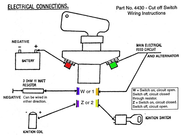
In answer to the multi-pole switch comment. The Pegasus is 3PST 2 poles are NO and 1 pole is NC.
The Red/Green and Violet/Yellow are N.O. and the Blue/Orange is N.C.
 Posting Permissions
- You may not post new threads
- You may not post replies
- You may not post attachments
- You may not edit your posts
-
Forum Rules


 Reply With Quote
Bookmarks